API Reference and Library Architecture

 |

|
Introduction
The RidgeRun Video Stabilization Library (RVS) is fully implemented in C++, using the 2017 C++ standard and the Google code style. From the design and architecture perspective, RVS is based on the interface-adapter design pattern (also known as Hexagonal Architecture).
This section will describe and explain each interface. Moreover, it will provide a general overview of the currently implemented adapters and the expected data flow along the interfaces.
Interfaces
The interfaces help RVS to keep the API along the multiple implementations of a single algorithm. For instance, the undistortion algorithm can be implemented using OpenCL, CUDA or CPU. However, it may break the API if it is not carefully guarded. RVS has several interfaces representing multiple objects, algorithms, allocators, and backends. This section will mention them and explain their purpose.
ISensor
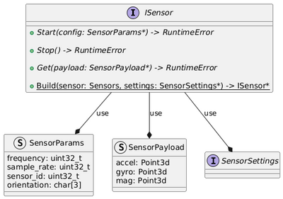
In charge of abstracting the IMU sensor communication. Through RAII, it performs the sensor initialization and termination.

It offers three main methods:
- Start: Starts the sensor readings if the sensor is based on a buffer pool or a reading thread.
- Stop: Stops the sensor readings if the sensor is based on a buffer pool or a reading thread.
- Get: Gets the last sensor readings
And the factory method Build.
To construct a new instance of the sensor, an implementation must be provided (available Sensors) and a settings object must be provided (according to the implementation selected). Each implementation must define its own SensorSettings implementation, which will help the implementation to configure the sensor as needed.
Then, the Start configures the sensor using the frequency, sensor id and the sample rate passed as SensorParams.
To get the readings, the Get method receives a valid SensorPayload object that fills the accelerometer (accel), gyroscope (gyro) and magnetometer (mag) 3D points.
Reference Documentation: ISensor
IImage and IAllocator
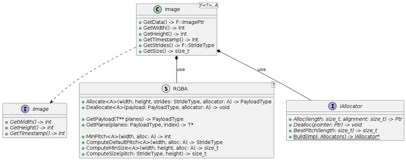
Interface for the image object implementation. This is an interface that allows abstracting an actual Image implementation. It can be seen at two levels: the runtime interface and the compile-time interface, which is strongly typed to avoid false and erratic implementations during undistorted algorithm programming.

The IImage interface is used only to conserve the Interface-Adapter principles, allowing the preservation of API uniformity and it is only recommended for interacting with the interface. The Image class is the recommended class. It receives two template arguments: F (Format) and A (Allocator).
The format is a templated structure, like RGBA<uint8_t>, where it implements all the properties required by the format, such as the number of planes, the pitch, strides, and others. It also requires the allocator provided by the A template for certain methods.
Starting from the IAllocator, it wraps the allocator and provides three functions:
- Alloc: allocates a buffer and returns the pointer.
- Dealloc: deallocates the memory from a pointer.
- BestPitch: determines the best pitch according to the default's alignment.
The format RGBA wraps the properties of the image format, receiving a datatype used to hold each channel value. The methods are:
- Allocate: allocates an image of a given dimension and strides.
- Deallocate: deallocates and frees the memory.
- GetPayload: converts an array of pointers to planes to the Payload managed by the Image class.
- GetPlane: gets a pointer to a given plane from a Payload.
- MinPitch: computes the minimum pitch from a width.
- ComputeDefaultPitch: same as MinPitch but invokes the allocator.
- ComputeMinSize: computes the min size using the width and height.
- ComputeSize: computes the size given the strides and height.
Finally, the Image class provides the following interface:
- GetData: returns an image pointer to the data.
- GetWidth: returns the image's width.
- GetHeight: returns the image's height.
- GetTimestamp: returns the image's timestamp.
- GetStrides: returns the image's strides per plane.
- GetSize: gets the image size.
The usage of this class is based on the creation of an Image object (which can receive external data from pointers) and then encapsulate it into a IImage pointer that is transferred with borrowed ownership. Moreover, inside of the undistort and other image processing algorithms, it is recommended to use the concrete Image objects rather than the IImage interface unless API compatibility shall be guaranteed.
Reference Documentation:
IImage,
Image,
IAllocator,
RGBA
IIntegrator
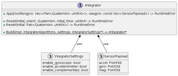
The integrator is in charge of softening the readings from the sensor. Moreover, it transforms the SensorPayload into Quaternions. There can be multiple integration techniques, such as trapezoidal integration, Riemann sums, VQF, and others. You can see more integration algorithms in Stabilization Algorithms with IMU.

It provides the following methods:
- Apply: integrates the data coming as SensorPayload and performs the conversion into quaternions representing the rotations.
- Reset: removes the history from the integration instance and resets the initial time and orientation.
And the following factory:
- Build: constructs an integration algorithm instance given some settings indicating the kind of data the sensor provides.
The integrator algorithm goes after the sensor readings and before the interpolation. The data rate is usually two times faster than the video rate to have enough data for interpolation. Moreover, it is placed before the interpolator to get the actual angles, given that the gyroscope provides angular velocities (the integral of the angular velocity is the angular position). Besides, some algorithms complement the gyroscope measurements to avoid biasing and enhancing the angular calculations.
Reference Documentation: IIntegrator
IInterpolator
The interpolator calculates the angle depending on the video frame and sensor reading timestamps. The angle is interpolated such that it matches the video movement. Moreover, it adjusts the angular data at the same rate as the video rate. The current interpolator uses the Slerp function, explained in Stabilization Algorithms with IMU.

The interface provides the following methods:
- Apply: interpolates the integrated quaternions to the angular positions that match the frame timestamps. The input vector usually contains more samples than the output vector.
- Reset: sets the current timestamp of the frame or resets it to an initial value.
And the following factory:
- Build: constructs an interpolator algorithm instance given some settings regarding the microsecond frame interval.
Interpolating the angles is crucial to have a track of the evolution of the angles at the time marked by the video frame. The output of the interpolation can be used to compute the quaternion to fix the image movement, leading to the stabilization process.
Reference Documentation: IInterpolator
IStabilizer
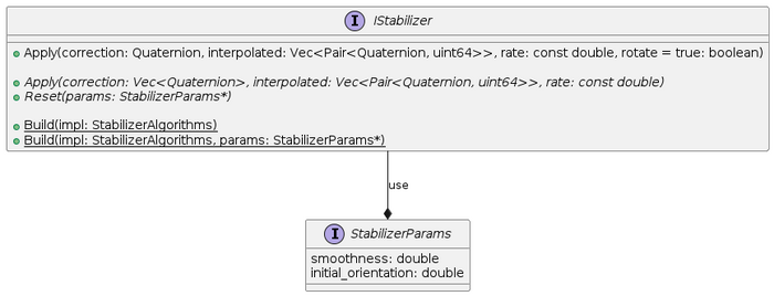
The stabilizer interface provides the API to correct the angle based on previous and future data. The stabilizer algorithms can be causal or non-causal, depending on the calculations. You can see the stabilization algorithms in Stabilization Algorithms with IMU.

It provides the following methods:
- Apply: applies the stabilization given a triplet of quaternions with (previous angle, current angle, and the next angle). It returns a quaternion that sets the correction needed to compensate for the movement.
- Reset: resets the stabilizer configuration and the initial orientation.
And the following factory:
- Build: constructs a stabilizer algorithm instance given some settings depending on the algorithm.
Please note that StabilizerParams is an inheritable class. Newer algorithms can specify their own set of parameters and must inherit from this interface structure.
After determining the correction, the next step is to apply the undistortion to compensate for the movement to stabilize the image.
Reference Documentation: IStabilizer
IUndistort
The undistort interface standardizes the API for the undistortion algorithms. These algorithms receive a quaternion with the deviated value that the undistortion process must correct. The undistortion consists of the pinhole camera model, which uses a focus length computed for the default lens and performs a rotation in the 3D space. It usually consists of two steps: map computation and remapping. The implementations are CPU-based through OpenCV and accelerated through GPU by using the backends.

It provides the following methods:
- Apply: performs the correction of the inframe based on the quaternion rotation. The resulting image is stored in outframe. The field of view scale can be modified through the fov.
- GetRuntimeSettings: returns a copy of the settings used by the undistort.
- SetRuntimeSettings: sets the settings used by the undistort. The settings must be available throughout the lifetime of the undistort.
It also facilitates the factory method:
- Build: creates a new instance of the undistort and allows setting the IRuntimeSettings.
The IRuntimeSettings are backend-specific settings, such as work queue or CUDA stream. It also stores information such as context or local workgroup sizes.
The undistort uses the backends, where each backend implementation leads to an Image type with a specific allocator and a new IUndistort instance. For instance, the IUndistort that uses OpenCL is called FishEyeOpenCL, whereas the OpenCV backend is implemented in the FishEyeOpenCV.
This is considered the last step of the stabilization process.
Reference Documentation:
IUndistort,
Image,
IRuntimeSettings
Data flow
The data flow along the different interfaces is homologous to the one explained in Video Stabilization Process using IMU.
You can find a complete example in Example Application.


